- Nuclear Reactors, Boilers, Machinery And Mechanical Appliances; Parts Thereof
- Automatic Data Processing Machines And Units Thereof; Magnetic Or Optical Readers, Machines For Transcribing Data Onto Data Media In Coded Form And Machines For Processing Such Data, Not Elsewhere Specified Or Included.
- Data-processing Machines, Automatic, Presented In The Form Of Systems "comprising At Least A Central Processing Unit, One Input Unit And One Output Unit" (excl. Portable Weighing <= 10 Kg And Excl. Peripheral Units)
Preliminary Technical Proposal for 300tpd Active
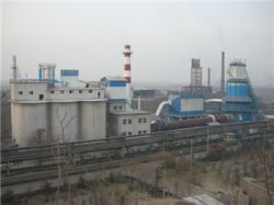
Product Images
Product Property
| Product Status : | New |
| Sample Available : | yes |
| Shipment Terms : | fob,cfr,cif,Negotiable |
| Payment Mode : |
T/T,L/C |
Description
This Preliminary Technical Proposal is made by Anshan Huajie Building Materials Technology R&D Co., LTD (hereinafter referred to as the Proposer) for establishing a 300tpd active lime production line in Zambia based on the requirement of Konkola Copper Mines plc, Zambia (hereinafter referred to as Client), and as some basic information is unavailable, some assumptions are taken as the basis of this Proposal, and they are subject to amendment during technical and contractual negotiation.
1. General Description
The project is to establish a 300tpd active lime dry type production line with rotary kiln, shaft preheater and shaft cooler. The annual production will be 100, 000 ton and the location of the project is in Zambia. The product of the production line will conform to China National Standard GB/Т042-99 and will be used for copper smelt. The production scale and main consumption index of the production line are given hereunder.
- Production scale: 100, 000 t
- Annual limestone consumption: 190, 000 t
- Annual electricity consumption: 3, 250, 000 kWh
- Annual HFO consumption (LHV=10, 300kcal/kg): 11, 650t
- Annual water consumption: 5395 m3
- Annual steam consumption: 887.4 t
- Annual nitrogen consumption: 150 m3
- Compressed air consumption: 4.2m3/min
2. Main Design Data
Based on the information the Client provided about specification of raw material, fuel, and product (active lime) together with the experience of the Proposer on similar projects, the main design data are given below which are subject to adjustment according to the real conditions of the project.
- Grain size of raw materials: 15~40mm
- Grain size of product (active lime) 0~40mm
- Heat value of HFO 10300 kcal/kg
- Specific heat consumption of per kg active lime 1200 kcal/kg-lime
- Specific electricity consumption of per ton active lime 32.5 kWh/t-lime
- Density of dust emission 50mg/m3
- Hourly production capacity 12.5 t/h
- Average annual workday 330 day
- Size of rotary kiln Æ3.5×55 m
- Size of HJ shaft preheater Æ8×3.2 m
- Size of HJ shaft cooler Æ3.6×7.5m
The specific electricity consumption for active lime production given above is calculated based on using HFO as fuel and the product without grinding, and in case pulverized product is required, 20 kWh/t-lime for product grinding shall be added over the figure given above.
3. Outline of the Technical Process and Auxiliaries
3.1. Raw material storing yard
Limestone with grain size of 15~40mm will be transported by truck or train to the plant and stored in raw material storing yard. The dimension of the yard is 60×15 m2 and the storing capacity can meet 5 days’ production requirement.
A wheel loader is used to load the limestone into the receiving hopper and then sent to limestone bin, which located on the top of the preheater, by 2.0 m3 single-bucket elevator. Dedusters are used at both receiving hopper and the top bin to restrain dust pollution.
3.2. Calcining section
3.2.1. Material flow
The limestone stored in the top bin is distributed into 8 preheating chambers of the shaft preheater, the size of the shaft preheater being Æ8×3.2m. Low pressure drop beam is set in the material channel of the preheater to lessen pressure drop of the flue gas. After being preheated by the hot flue gas of about 1100°C, the temperature of the material reaches 800~900°C and about 30% of the limestone is decompounded; and then the preheated material is pushed out by hydraulic pusher and enters into the Æ3.5×50m rotary kiln through transfer chute. The material is further calcined in the kiln until all of the limestone is decompounded, and then the well calcined active lime will enter the shaft cooler. After being cooled by the air blown from the bottom of the cooler, the active lime will be discharged by electromagnetic vibrating discharger, and then the cooled active lime will be sent into lime silo by bucket conveyer. Finally the products will be transported out of the factory by truck, bulk loader being equipped for loading the truck.
3.2.2. Flue-gas/air flow
The hot flue gas produced by the combustion together with the CO2 generated from the decompounding process will enter the shaft preheater, and after preheating the limestone, the waste gas will pass HJ heat exchanger and deduster and be discharged into the air by exhaust fan. The dust density of purified gas will be less than or equal to 50mg/Nm3.
The hot air coming from the lime cooler with temperature of 600~700°C will enter the kiln hood as secondary air for the combustion in the kiln.
3.2.3. Fuel system
HFO is used as fuel of lime production. The LCV of the HFO is determined as 10300kcal/kg.
One HFO storage tank with volume of 328m3 will be set up, the capacity of the tank is 262.5t which can meet 7 days’ production requirement. The HFO in the tank will first be heated to 80°C, and then sent by pipeline to the burner to satisfy the requirement of lime calcinations.
3.3. Flue gas cleaning system of rotary kiln
According to the flue gas design data of rotary kiln, the temperature and flow rate of the flue gas at the outlet of the preheater are about 280°C and 56800Nm3/h respectively. Based on the design scheme, the primary air of the combustion system shall be preheated to 200°C in heat exchanger located between the preheater and the deduster. After heat exchanging, the cooled down waste flue gas will enter the deduster, and after dedusting, the purified flue gas will be emitted into the air through draught fan and chimney. The dust content of the purified flue gas will be less than or equal to 50mg/m3.
The dust collected by the deduster will be sent into dust bin through rotary discharger and chain conveyer, and the dust stored in the bin will be periodically transported out of the factory by truck. To ensure the dust smoothly discharged from the dust hopper of the deduster and prevent adhesive bonding on sidewall, the dust hopper is equipped with vibrating rapper, and for dew avoiding, heat insulation measure is taken for the hopper.
3.4. Water supply and drainage
The water source is excluded in this project and the Client shall connect the water supply pipeline to the project site and ensure the required water supply parameters, i.e. water quality and pressure and flowrate, at the receiving point which is one meter inside the boundary line of the factory.
In this factory, production and fire water system, domestic water system and cooling water circulating system will be set up.
Domestic water and production-water/rain-water will be drained respectively by two individual drainage systems.
3.4.1. Water supply system of production and fire fighting
Water supply system of production and fire fighting will be connected from the water receiving point. The water pressure at the receiving point should be not less than 0.3MPa. To ensure the reliable water supply, two water supply mains are required. In the factory, circular water supply pipelines are adopted to supply water to each water consuming point. Fire fighting water system is planned based on putting out one fire. The water flowrate of outdoor fire fighting will be 15 L/s and 5 L/s for that of indoor.
Make-up water for production water system is 2.8 t/h.
3.4.2. Domestic water system
The receiving point of domestic water system will be one meter inside the boundary of the factory. The water pressure at the receiving point shall be >0.25MPa. One water supply main is required, and in the factory, the dendritic water supply pipeline is used for domestic water supply.
The daily domestic water consumption is 8.2 t.
3.4.3. Cooling water circulating system
To save water, cooling water circulating system is used for kiln support rollers, hydraulic system, fans and air conditioner etc., and the maximum circulating water quantity will be 28m3/h. A pump house with mechanical draft cooling tower will be set up for the system.
3.4.4. Drainage systems
One common drainage system will be set up to drain both the waste water of production and rain water.
Domestic waste water drainage quantity is 8.17t/d.
3.5. Electric and telecom
3.5.1. Electric system
To ensure reliable power supply, two 10 kV power supply circuits are required, and one substation will be set up for the factory. The substation will be equipped with one 10/0.4/0.23kV transformer, the capacity of the transformer being 1250 kVA. Three electric rooms will be set up for the factory.
MT motor will be used for the main draft fan of the kiln, the voltage being 10kV while the capacity being 335/160 kW, and the MT motor will be connected to the 10 kV bus bar.
3.5.2. Illumination and lightning protection
New type power saving lamp will be mostly used for illumination of the factory building, the voltage will be 220V, while fluorescent lamps are used for operating rooms and rest rooms, and for maintenance lighting, safety voltage of 36V will be adopted.
Lightning protection system will be designed in accordance with relative Chinese design criteria, i.e. for the second kind buildings and structures, taking measures to prevent direct lightning strike and lightning induction damage, while for third kind buildings and structures, to prevent direct lightning strike only.
3.5.3. Telecom
The telecom system includes communication system and fire alarm system.
Communication system: one telephone system will be set up for normal communication and production dispatching. And for important production posts, interphone (without host) will be set up.
Fire alarming system will be set up in the substation, electric room and CCR.
3.6. Control system
An integrated control system of electric, instruments and computer will be set up to ensure the proposed production line could run smoothly and reliably.
3.6.1. Function of the control system
The system mainly has following functions:
- monitoring the running state of the production line,
- collecting signals of equipment for on/off and abnormal running state,
- detecting and regulating the production parameters of pressure, flowrate and temperature,
- forming and displaying various flow chart and process chart,
- setting up production parameters and giving operation order,
- printing various reports,
- alarming while abnormal state occurred.
3.6.2. Main instruments and detecting points
a) Raw material system and final products system
- high/low material level meter for bins and silos to alarm abnormal state,
- electronic weighing device for belt conveyor of raw material and final products;
b) Calcining system
- pressure regulation of kiln outlet,
- proportional regulation of primary air flowrate,
- measurement of temperature, pressure, flowrate, water level, material level and differential pressure in preheater and lime cooler, and necessary interlock,
- measurement of temperature, pressure and flowrate of deduster, and necessary interlock;
c) HFO system
- measurement of temperature, pressure, flowrate and flameproof of HFO system, and necessary interlock.
4. Major Technical Characteristics
4.1. Shaft preheater
As the working temperature of the proposed shaft preheater is higher than that of the others, sufficient preheating is realized in the preheater, the raw material can be preheated to 900°C and about 30% limestone can be decompounded in the preheater. For this high efficiency design of the preheater, the outgoing temperature of the flue gas is relatively lower. Compared with other kinds of rotary kiln, the proposed kiln system is featured with lower heat consumption of 1200kcal/kg-lime.
The proposed shaft preheater is of low pressure drop type, the pressure drop being about 60% of the normal one. As hydraulic pusher is used for charging the kiln from the preheater, it enhances the reliability of the system. Because of the using of material level meter in the top bin of the preheater, it ensures the stability of the height of the material layer in the preheater. Compared with other preheaters, the proposed one has the advantage of less moving equipment and therefore of less maintenance.
4.2. Rotary kiln
The rotary kiln is equipped with shaft preheater and shaft cooler. Cone shape design is adopted at the inlet and outlet segments of the kiln, which can properly increase the residence time of the material in the kiln. The guard plate of kiln hood is of air-cooling type and spring leaf type sealing is applied at both ends of the kiln.
Multi-channel HFO burner will be applied, and the flame profile can be optimized, therefore, .the combustion efficiency is improved.
4.3. Shaft cooler
Cooling air and hot lime contact directly for heat exchanging. The temperature of secondary air can be heated to more than 600°C and it is helpful for calcining. The proposed cooler has the advantage of no moving equipment and therefore of less maintenance.
4.4. Pyrological control
The control system based on PLC with functions of regulation, control and alarm is used for the production line, which makes centralized control realized in the CCR and features with modern control level.